Because Tom asked me this summer, I created an English version of this instruction. Thanks to Tom for his help with the translation. As I'm no native speaker I would appreciate any comment
on my grammar or the words I use.
To give you a brief summary of the upper German page, I added these paragraphs:
The issue started when my Jura IMPRESSA S95 didn't stop to ask for the cleaning program. My wife found the pages of XXX* and we bought the "Rundum sorglos Paket XXL". It worked fine, however
I decided to create this instruction. The two pictures on the upper German page show the state of the machine after 1800 cups of coffee and the normal cleaning program. If you have any
questions about this instruction, please name the number of the picture, shown below the picture, as a reference.
At this point I want to thank you for all the friendly emails I receive. I enjoy them much and they encourage me to keep these pages in good shape.
General Information
At the first cleaning (11/18/2002), when these pictures were taken, I replaced all three O-rings with the ones from the "Rundum sorglos Paket XXL". Then I had to apply lubricating grease
about every 200 cups. I was lucky to save the original O-rings after that first cleaning. Later (04/14/2003) I replaced the two bigger O-rings with the original ones. After that change,
the normal interval rates returned (01/05/2004 : 750 cups without any service).
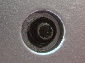
Picture 00
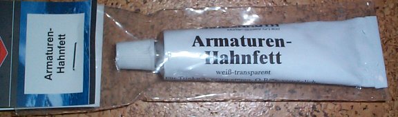
A technician from the Jura service gave the hint to use lubricating grease for drinking water fittings. It is compatible to the O-rings, hot water resistant up to +180°C and you can get
it from any do-it-yourself store at a reasonable price. He suggests to put lubricating grease only on the O-rings and the long gearwheel. All other moving parts do not need lubrication,
as plastic slides on plastic. Grease attracts coffee powder that would slow down the machine.
Andreas uses an old toothbrush and the small vacuum cleaner nozzle for cleaning and reapplying lubricating grease through the pre-ground coffee filler funnel (without dismantling the machine).
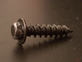
Rainer told me, his S95 has Torx screws instead of Philips screws.
Sven bought the replacement for his boiling part at the online shop of http://www.trepesch.de. Until further notice, I show this link with permission
of the Trepesch GmbH. Unfortunately this shop stopped the support of Jura machines either (2010).
Rainer bought Viton O-rings at Mordhorst + Bockendahl from Kiel. He paid €13,= for 2 rings 1.8 x 3.9, 2 rings 3.5 x 37 (upper cylinder) and 2 rings 3.5 x 35 (lower cylinder). The rings
are heat resistant and will run for a long time.
For the ones of you, who seek instructions for a Saeco machine, the Author permitted me to advertise the page of
Sergio Schreiber.
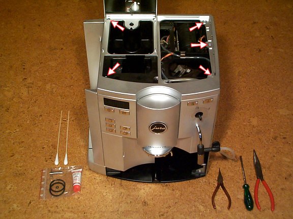
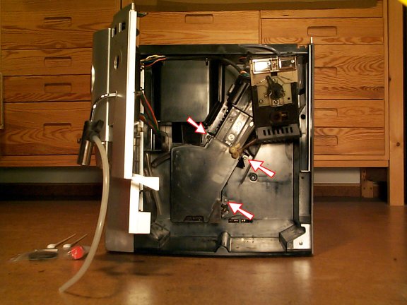
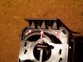
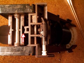
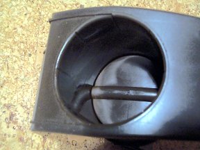
After a period without usage (3 weeks of holidays) I had to fix an error. During the short cleaning no water ran out of the coffee dispenser. The pump seems to create the appropriate
pressure. After that my S95 asked to request steam to fill the machine with water. Hot water for tea could be taken without any problem. After completely cleaning the machine and some more
tries I found a stopper within the pipe (picture 03, top, middle, front) that was not visible at all. It appeared when I removed the pipe from the water valve. I removed it with a needle.
Now it works fine again.
More than once I was asked how to open the rear part of the machine with all the electrical parts. I have to state clearly that this area is reserved for trained people only.
There is a hazard of an serious electrical shock! For that reason the cover is fixed with special screws with an oval head.
Beside that I'd like to thank Erika & Jürgen, Reinhard, Mara, Norbert, Uwe, Patrick, Jörn, Ralf, Thomas, Markus, John, Silje und Geir, Michael, Joris, Reinhold, Andre, Christian,
Jürgen, Jörg, Hans-Josef, Valentin, Sven, Volker, Bernd and all the others from Germany, France, the Netherlands, the Swiss, Norway and the US for the kind words.
For those, who's questions I did not answer I kindly ask to apologies my lack of time.
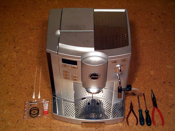
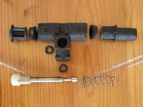
Picture 01
We start here. Left of the S95 you can see the "Rundum sorglos Paket XXL" of XXX*. On the right side you can see the tools I use. A Philips screwdriver and a normal screwdriver
to open the latches. The Long-Nose pliers on the right side is used to pull the clamp. The small pliers on the left side isn't used at all. You need to vacuum clean with a small
nozzle to get rid off the coffee residue.
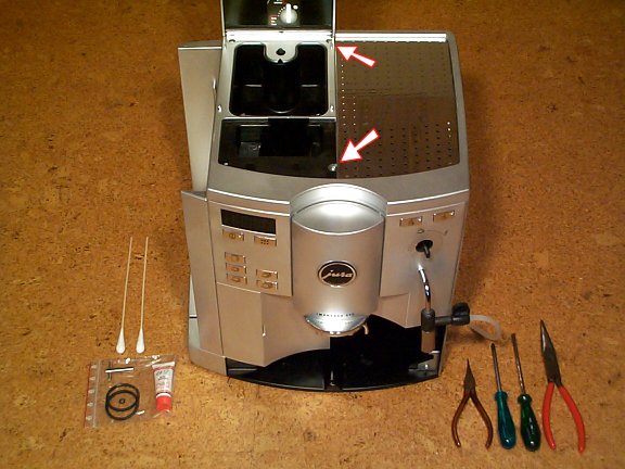
Picture 02
First remove the water tank, then the drip tray, the pre-ground coffee filler funnel and the cover for the bean container. You have to pull off the two knobs "grinding selector
panel" and "selector panel for coffee or hot water". When you remove the two screws you can remove the heating plate.
Picture 03
Now it's time to remove the top cover of the machine. Please be careful after taking the screws out with removing the panel.
Picture 04
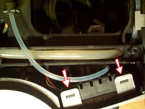
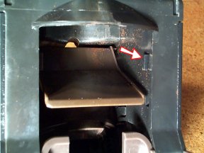
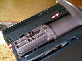
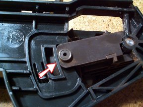
The next step is the front door. You have to remove the screw in the area of the drip tray. Please regard the small nib on the right side, that fits into the door. You have to watch this
when you reassemble the machine. It must fit into the whole at the door.
By the way, in the left lower corner of this picture you see the two plugs for the contacts shown in Fig. 8 of the Jura Instruction for use. Therefore the contacts are on the rear side of
the drip tray.
Picture 05
Remove the "selector panel for coffee or hot water" from the front door by carefully inserting a screwdriver between the two clips on the door. While you topple the "selector panel for
coffee or hot water" backwards, you can pull out the pivoting nozzle for hot water/steam.
Picture 06
Now it is possible to open the door a little farther in order to remove the hoses from the coffee- and tea-spout. You have to bend the clips a little. But take care again.
Picture 07
Now we are done. The door can be opened completely. When you open the door towards 90° the wires are stretched and there is a dead stop. I suggest to avoid to open it further on. ;-)
Picture 07 a
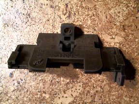
Kerstin, this is the way to unmount the coffee dispenser. Unlock the four clamps at the door.
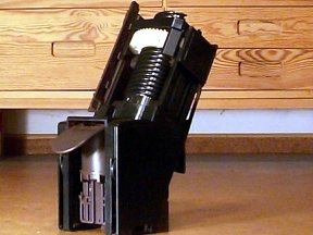
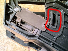
Picture 07 b
The coffee dispenser is disassembled by lifting the latch. With this you seperate the upper part from the lower part. The insert has to be removed from the lower part.
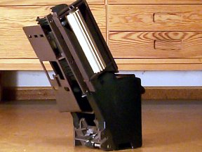
Picture 07 cPicture 07 dPicture 07 ePicture 07 fPicture 07 g
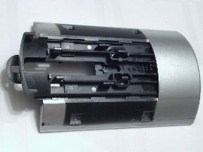
Now it is possible to clean the lower part.
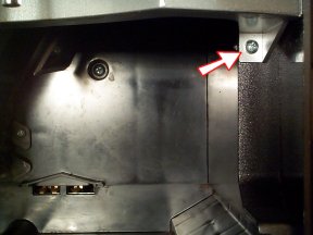
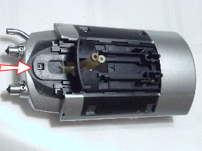
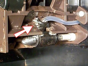
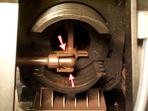
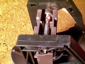
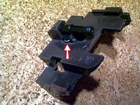
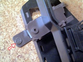
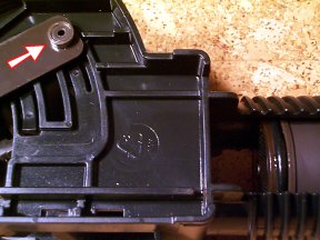
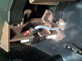
Picture 08
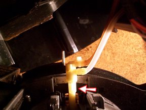
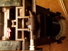
Although you might not believe it, there is a clamp at the tip of the arrow. This clamp fixes the hose into position and is removed by pulling it to the front of the machine.
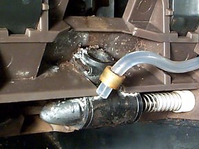
Picture 09
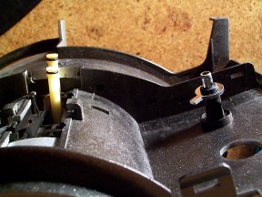
As you pull the hose out, an O-ring stays inside. This is the O-ring, I replaced with a new one.
Rainer told me, that his machine has a ring of copper and it had verdigris on its surface. He used hot air (100°C) to heat the area. Then he could remove the hose.
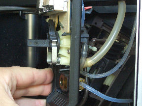
Picture 10
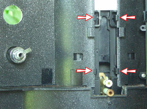
Two more clips to carefully bend, with a screwdriver, to remove the tiny pipe at the top of brewing unit.
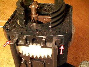
Picture 11
Now we have to remove the brewing unit. It is fixed with three screws. When these screws are removed, the whole part can be slid down and to the left to get it from behind the
"selector panel for coffee or hot water".
Picture 12Picture 13
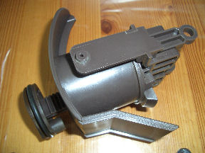
Here it is!
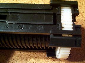
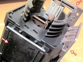
Picture 14
The long gearwheel can be slid off to the top. CAUTION: The gearwheel fits in one way only. You have to remember it's position. The cover above the big white gearwheel, opposite
to the long gearwheel, is clipped in. The guiding plate must be bend outside at it's top to loosen it. Now you can slide it down to remove it.
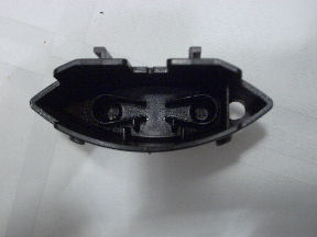
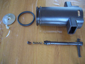
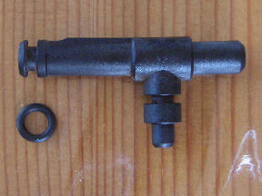
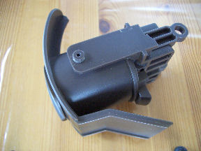
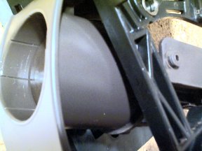
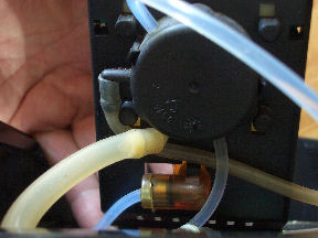
Picture 15
Pull off the cap to the top by slightly bending all four corners outward to release the notch. The angled plastic pipe is pulled off the vertical pipe. The position of the vertical
pipe defines the position of the cap during reassembling.
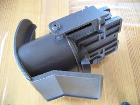
Picture 16Picture 17
The front and the rear cover is removed by opening four clips for each cover.
Rainer, you are right.
You should start with the fourth clip, that is not shown in these pictures.
Be careful, the metal spacers from the outer guiding of the topple mechanic will fall down now. They must be placed back during reassembly.
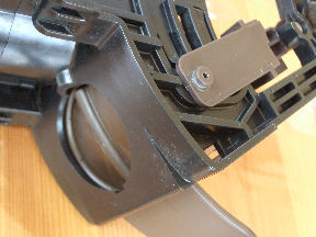
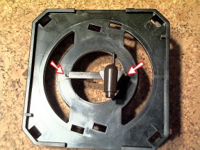
Picture 18Picture 19Picture 20
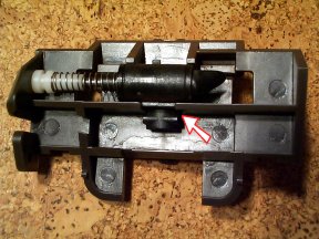
To remove the lower water supply from the brewing unit, the topple mechanic must be moved to the shown position. Turn the big white gearwheel. Be careful with the direction.
The topple mechanic can be moved in one direction only. When the topple mechanic has reached the shown position the lower water supply shall drop down without any force.
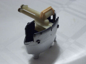
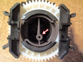
Picture 21
The water supply can now be removed from the slider. CAUTION! The white plastic part will jump off immediately. I used the picture of the cleaned piece to be able to show the details.
Picture 21 a
Once I had a service for my brewing unit. With that change I got this water valve. It combines more parts, but it's more easy to clean. When the valve is removed, it falls into peaces.
Picture 22
Now remove the two snap rings from the axis of the topple mechanic. Use a screwdriver to pull them off. The next step is to push the axis through the bearing to one side. In our
machine one end of the axis was covered with rust. I had to use a wooden punch and a hammer to get it out. But I had to be careful also, plastic parts break easily. The brown plastic
parts of the topple mechanic can be turned in such a way to release the tube with the pusher to the top. Now the lower part with the six gearwheels must be twiddled out of the black
plastic part. Without using force it is a little difficult, but it is possible.
Picture 23
The two side plates that cover the big white gearwheel can be pulled out off the bushing right below the gearwheel. Now the gearwheel is free to remove the brown inner pieces of the brewing unit.
Picture 23 aPicture 23 b
The slide can also be disassembled. The coffee pipe can be removed by turning it. With this the spring and the plug are released. The filter is released by removing the screw.
Robin, here is one of the large O-Rings.
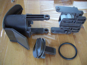
Picture 24
That's it. Everything is disassembled and you can start to clean each piece. I used a vacuum cleaner, hot water and a brush with plastic bristles.
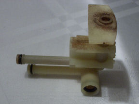
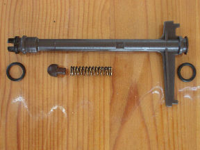
Picture 25
We start with this piece. It is the lower water dispenser of the brewing unit. You put an O-ring with a thin cover of lubricating grease into the short connector. The long connector
will get the new O-ring later.
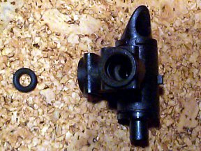
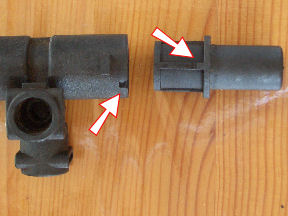
Picture 25 aPicture 25 b
If someone is having this type of water valve, it is important that only one side is having a notch. At this side the output to the drip pan is placed fitting into the notch.
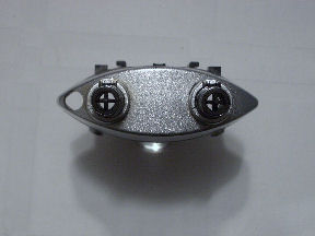
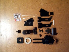
Picture 25 c
This picture is showing all parts of the water valve unit.
Picture 26Picture 27Picture 28
On the front of the slider fit in the long connector of the water dispenser. On the rear of the slider fit in the angled pipe. Both pieces are fixed with a clamp.
Picture 28 a
Now the cylinder with the lower slide is assembled. This picture is showing all parts.
Robin, here is the second large O-Ring.
Karsten, these pictures are showing the correct assembly of the parts. It fits when the part with the gearwheel is moved to the top most position (towards the cylinder)
to insert the slide.
Bild 28 bBild 28 cBild 28 dBild 28 e
The smaller O-ring is mounted on the lower pusher of the brewing unit. Put lubricating grease into the notch to cover the whole O-ring. The pusher is placed inside the tube that
will hold the coffee powder.
Picture 29
The smaller O-ring is mounted on the lower pusher of the brewing unit. Put lubricating grease into the notch to cover the whole O-ring. The pusher is placed inside the tube that
will hold the coffee powder.
Picture 30
Now you twiddle in the lower part with the six gearwheels. It's a good idea to put one arm into the opening as shown in the picture. The inner the metal spacers get a cover of
lubricating grease before they are mounted.
Picture 31
With the next step you place the tube with the pusher into the six gearwheels. It is important that the pusher can reach both end positions. Planar with the upper edge of the
tube and with contact to the stop position at the lower end of the tube. If it doesn't match, the pusher will drop of the upper end of the tube. Now put in the axis and fix it
with the two snap rings. To ease the next remove of the axis, put little lubricating grease around each end.
Picture 32
At this point you can check the movement of the topple mechanic. It is important that the nib fits into the notch. Otherwise the water dispenser isn't sealed when the brewing
takes place. Unfortunately the brown parts can also be put in in the other direction.
Picture 33
The larger O-ring is mounted on the upper pusher of the brewing unit. The pusher is placed inside the screw thread. This notch needs lubricating grease too, to cover the O-ring.
After that, you must move the topple mechanic into the shown position. Now you place the metal spacers on the outer guiding of the topple mechanic together with some lubricating grease.
Picture 34
Screw the big white gearwheel onto the thread and push the two side plates into their bushing right below the gearwheel. Don't lose the metal spacers during that step!
Picture 35Picture 36
Snap in the two side covers.
Picture 37
Snap in the angled pipe into the notches of the cap. As it is symmetric, there is no wrong way to do it.
Picture 38
With the mounted angled pipe, the position of the cap at the top of the brewing unit is defined. Each four corners must snap into a notch.
Picture 39
Now slide in the long gearwheel and snap on the guiding plate. With the black cover plate the horizontal pipe is kept in place (not shown in this picture). As mentioned earlier,
the long gearwheel fits in only one direction. At this point the mounting of the brewing unit is finished.
Picture 40
The brewing unit is placed into the machine and fixed with three crews.
Picture 41
This step is a little difficult. The lower water hose with the O-ring must be inserted and fixed with the clamp. To prevent the copper ring from getting verdigris on its surface,
cover it with a little lubricating grease. By the way, this is the small O-ring I replaced with a new one.
Picture 42
The O-ring inside the upper water supply gets a little lubricating grease and the pipe is connected and fixed with the two clips.
Picture 43
The two O-rings get a little lubricating grease too, and the hoses are reconnected with the coffee- and tea-spout and fixed with the clip.
Picture 44
The two O-rings on the pivoting nozzle for hot water/steam get a little lubricating grease and the nozzle is pushed into the "selector panel for coffee or hot water".
The "selector panel for coffee or hot water" is fixed with the two clips at the door.
Picture 44 aPicture 44 b
For Christian and Armand I add detailed pictures of the selector in case someone has removed all hoses.
Picture 45
Now close the front door. Please take care of the nib that must fit into the notch in the wall. Otherwise you can not close the door. The door is fixed with the shown screw.
Picture 46
The top cover of the machine follows with the five crews ...
Picture 47
... and the heating plate.
Picture 48
Put on the knobs, place the pre-ground coffee filler funnel and the water tank and you are ready. The coffee machine is in one piece again.
XXX* suggests to run the cleaning program once to remove spare lubricating grease. I have done this without a cleaning tab and I didn't notice a difference in the taste of
the first cup of Espresso. Now it is working again and everyone is pleased.
Congratulations! You have earned the official do-it-yourself certificate!
The ones of you, who own a Windows Mediaplayer, can listen to the sound of the cleaning program: Spuelen.wma (102KB)
* Via email I was asked to remove any appearance of the name and the website which I did with this change.